

Your Professional PLC Enclosure Manufacturer
KDM PLC Enclosure is suitable for a range of PLC control systems such as Allen Bradley PLCs, Mitsubishi PLCs, General Electric (GE) PLCs, ABB PLCs, Siemens PLCs, Hitachi PLCs, Decowell PLCs, etc. Our PLC enclosures come in different designs, configurations, and layout designs to house both PLC and SCADA control panels. At KDM Steel, we know industrial control systems play a major role in the modern automation and efficient production process.
With our 10 years plus experience in the electrical enclosure manufacturing industry, our technical team chooses the finest material, while using appropriate cutting equipment and fabrication technologies.
KDM PLC Enclosure Series


Send your Inquiry on KDM PLC Enclosure
Whether you need a PLC enclosure with lock/latching options, easy-to-access pushbuttons, dual access, multiple doors, or window options, KDM Steel offers high-quality and affordable PLC enclosures.
KDM Steel engineers will take you through the 2D and 3D Computer-Aided Design or design concepts for your PLC Enclosure. Talk to our engineers today for custom-made PLC Enclosure.
- Manufacturing Capacity
- Buying Guide
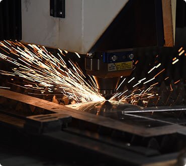
4000W high-performance laser cutting machine, +/- 0.05mm accuracy. No burr, no scratching.

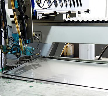
Multi-Functioning flexible welding equipment, high accuracy, no deformation.
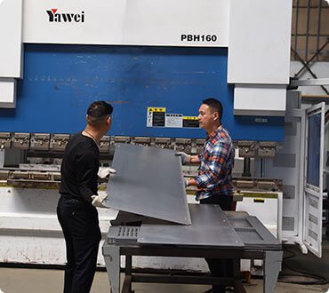
+/- 0.5mm bending precision, smooth surface without bending marks.

10+ welding experienced workers, perfect overall appearance.
High speed and accuracy foaming machines, fast and qualified Gasket

The expert assembling team, consistent assembly quality on every KDM enclosure
KDM: Your Professional PLC Enclosure Manufacturer
Depending on the type of application, KDM PLC Enclosure comes as an indoor electrical enclosure or outdoor electrical enclosure.
Unlike most electrical enclosure manufacturers in the market, KDM PLC Enclosures are made for specific environments.

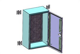
PLC Enclosure Welding
Available options may include NEMA Type 1, 2, 3, 3R, 3S, 3X, 3RX, 3SX, 4, 4X, 5, 6, 6P, 7, 8, 9, 10, 11, 12, 12K or 13 enclosure.
Moreover, the KDM PLC Enclosure comes as free-standing PLC enclosure, wall mount PLC enclosure, modular PLC enclosure, weatherproof PLC enclosure, PLC enclosure with window, vented PLC enclosure, among other designs.
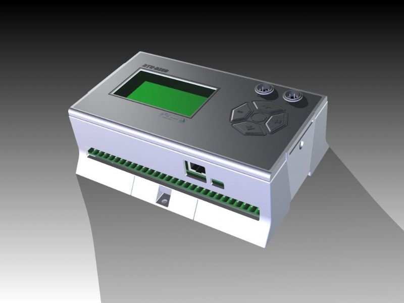
KDM PLC Enclosure is easy to install or access, may have quick power ON/OFF button on the door, small screen for monitoring or control processes, LED indicators on the panel and easy cable or wire management design.

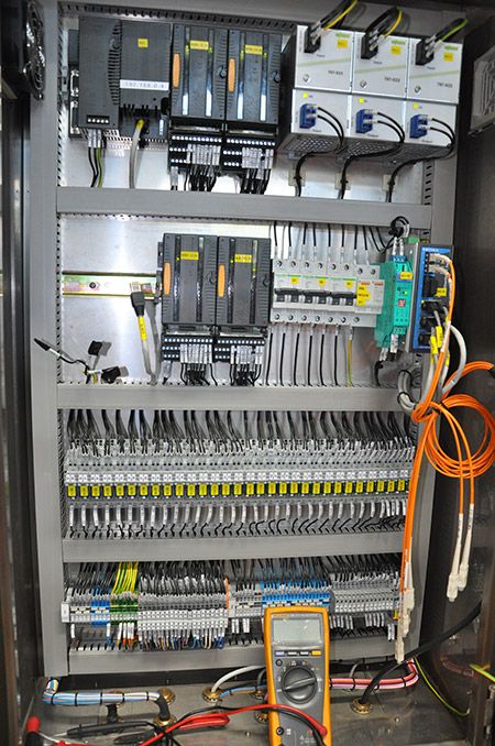
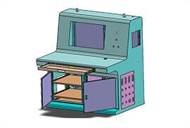
PLC Enclosure Accessories
KDM PLC Enclosure, also names PLC Cabinet or PLC Panel Enclosure, is CE, RoHS, IEC and NEMA compliant accessory made from steel, galvanized steel or stainless steel (304.316L).
It is specifically designed to house all industrial control panels and CPUs to ensure safety and protection.
A reason why KDM PLC Enclosure is uniquely designed to protect all sensitive control systems.

PLC Enclosure Manufacturing
PLC Enclosure – The Full FAQ Guide
Automation of manufacturing and industrial processes is the key point of each successful facility.
To make the processes as flawless as possible, PLC systems were introduced.
In this article, we would try to explain how such systems work and why they need the most robust enclosures to do so.
- What Is a PLC?
- How PLC Works?
- What Types Of PLC Enclosures Can KDM Offer?
- Can You Describe The Electrical System Where PLC Enclosure Is Used?
- What Kind Of Mounting Options Do I Have With KDM PLC Enclosures?
- Can You Name Materials Used To Manufacture PLC Enclosures?
- How To Test The Safety Of PLC Enclosures Against Hazardous Environmental Effects?
- What About The Noise And Heat Management of PLC Enclosure?
- Do I Have To Check The Conditions Of PLC Before Starting It?
- How To Effectively Maintain PLC Enclosure And Inner Components?
What Is a PLC?
A programmable logic controller (PLC) is an industrial digital computer which has been created and adapted for the control of manufacturing processes.
PLCs were first developed in the automobile manufacturing industry to provide flexible and easily programmable controllers to replace hard-wired relays, timers, and sequencers.
Since then, they have been widely adopted as high-reliability automation controllers suitable for harsh environments.
PLCs can range from small modular devices with a dozen of inputs and outputs (I/O), in a housing integral with the processor, to large rack-mounted modular devices with a count of thousands of I/O, and which are often networked to other PLC and SCADA systems.
They can be designed for multiple arrangements of digital and analog I/O, extended temperature ranges, immunity to electrical noise, and resistance to vibration and impact.
Programs to control machine operation are typically stored in battery-backed-up or non-volatile memory.
When digital computers became available, being general-purpose programmable devices, they were soon applied to control sequential and combinatorial logic in industrial processes.

How PLC Works?
A programmable logic controller can’t work on its own – it requires special software in the form of operating programs.
Such programs are typically written in a special application on a personal computer, then downloaded by a direct-connection cable or over a network to the PLC.
The program is stored in the PLC either in battery-backed-up RAM or some other non-volatile flash memory.
Often, a single PLC can be programmed to replace thousands of relays.
In the early days of PLCs, programs were stored on cassette tape cartridges.
Facilities for printing and documentation were minimal due to a lack of memory capacity.
The oldest PLCs used non-volatile magnetic core memory.
More recently, PLCs are programmed using application software on personal computers, which now represent the logic in graphic form instead of character symbols.
The computer is connected to the PLC through USB, Ethernet, RS-232, RS-485, or RS-422 cabling.
The programming software allows entry and editing of the ladder-style logic.
In some software packages, it is also possible to view and edit the program in function block diagrams, sequence flow charts, and structured text.
Generally, the software provides functions for debugging and troubleshooting the PLC software, for example, by highlighting portions of the logic to show current status during operation or via simulation.
The software will upload and download the PLC program, for backup and restoration purposes.
In some models of programmable controller, the program is transferred from a personal computer to the PLC through a programming board that writes the program into a removable chip such as an EPROM.
Under the IEC 61131-3 standard, PLCs can be programmed using standards-based programming languages.
The most commonly used programming language is the Ladder diagram (LD) also known as Ladder logic.
It uses Contact-Coil logic to make programs like an electrical control diagram.
A graphical programming notation called Sequential Function Charts is available on certain programmable controllers.
A model that emulated electromechanical control panel devices (such as the contact and coils of relays) which PLCs replaced.
This model remains common today.
IEC 61131-3 currently defines four programming languages for programmable control systems: function block diagram (FBD), ladder diagram (LD), structured text (ST; similar to the Pascal programming language), and sequential function chart (SFC).
These techniques emphasize the logical organization of operations.
While the fundamental concepts of PLC programming are common to all manufacturers, differences in I/O addressing, memory organization, and instruction sets mean that PLC programs are never perfectly interchangeable between different makers.
Even within the same product line of a single manufacturer, different models may not be directly compatible.

What Types Of PLC Enclosures Can KDM Offer?
There are several approaches on how to categorize PLC enclosures.
First of all, the two main types of PLC are fixed: compact PLC and modular PLC.
Compact PLC comes within a single enclosure with many modules stored in one case.
It has a fixed number of I/O modules and external I/O cards.
So, it does not have the capability to expand the modules.
Every input and output would be decided by the manufacturer.
Modular PLC permits multiple expansion through modules, where I/O components might be increased.
It is easier to use because each component is independent of each other.
According to the physical size, PLC enclosures can be divided into mini, micro and nano PLC.

Can You Describe The Electrical System Where PLC Enclosure Is Used?
PLCs are mainly used on manufacturing and industrial sites where the automation of processes is required.
As we said above, programmable logic controllers were created to operate various processes while manufacturing automotive products, i.e. assembly lines, or robotic devices.

What Kind Of Mounting Options Do I Have With KDM PLC Enclosures?
KDM PLC enclosures can come as:
- Free-standing fixtures.
- Floor-mounted fixtures.
- Wall-mounted fixtures (including pole-mounted).

Can You Name Materials Used To Manufacture PLC Enclosures?
Mainly, KDM specialists use stainless and carbon steel to manufacture PLC enclosures.
However, if required, other materials might be used (such as various types of plastic, fiberglass, aluminum, etc.)

How To Test The Safety Of PLC Enclosures Against Hazardous Environmental Effects?
In order to test the ability of the enclosure to withstand corrosion, it is exposed to Ammonia gas.
The ISA G3 corrosion test included exposure to ammonia at a concentration of 25 parts per million for a continuous period of 30 days.
Note that such tests are done without the equipment being mounted in an enclosure (ie, direct pollution of the modules and carriers).
Hence, this is equivalent to a much longer installed lifetime within a cabinet, with occasional exposure to the gas due to opening of the enclosure door, or seepage at lower concentration into the enclosure.
Also, the enclosure might be tested in accordance with IP and NEMA standards.
If you wish to learn more about these tests, please, visit the following page.

What About The Noise And Heat Management of PLC Enclosure?
Implementation of the previously outlined recommendations should provide favorable operating conditions for most programmable controller applications.
However, in certain applications, the operating environment may have extreme conditions that require special attention.
These adverse conditions include excessive noise and heat and nuisance line fluctuations.
This section describes these conditions and provides measures to minimize their effects.
Excessive Noise
Electrical noise seldom damages PLC components, unless extremely high energy or high voltage levels are present.
However, temporary malfunctions due to noise can result in hazardous machine operation in certain applications.
Noise may be present only at certain times, or it may appear at widespread intervals.
In some cases, it may exist continuously.
The first case is the most difficult to isolate and correct.
Noise usually enters a system through input, output, and power supply lines.
Noise may also be coupled into these lines electrostatically through the capacitance between them and the noise signal carrier lines.
The presence of high-voltage or long, closely spaced conductors generally produces this effect.
The coupling of magnetic fields can also occur when control lines are located close to lines carrying large currents.
Devices that are potential noise generators include relays, solenoids, motors, and motor starters, especially when operated by hard contacts, such as push buttons and selector switches.
Analog I/O and transmitters are very susceptible to noise from electromechanical sources, causing jumps in counts during the reading of analog data.
Therefore, motor starters, transformers, and other electromechanical devices should be kept away from analog signals, interfaces, and transmitters.
Although the design of solid-state controls provides a reasonable amount of noise immunity, the designer must still take special precautions to minimize noise, especially when the anticipated noise signal has characteristics similar to the desired control input signals.
To increase the operating noise margin, the controller must be installed away from noise-generating devices, such as large AC motors and high-frequency welding machines.
Also, all inductive loads must be suppressed.
Three-phase motor leads should be grouped together and routed separately from low-level signal leads.
Sometimes, if the noise level situation is critical, all three-phase motor leads must be suppressed.

Excessive Heat
Programmable controllers can withstand temperatures ranging from 0 to 60°C.
They are normally cooled by convection, meaning that a vertical column of air, drawn in an upward direction over the surface of the components, cools the PLC.
To keep the temperature within limits, the cooling air at the base of the system must not exceed 60°C.
The PLC components must be properly spaced when they are installed to avoid excess heat.
The manufacturer can provide spacing recommendations, which are based on typical conditions for most PLC applications.
Typical conditions are as follows:
- 60% of the inputs are ON at any one time;
- 30% of the outputs are ON at any one time;
- the current supplied by all of the modules combined meets manufacturer-provided specifications;
- the air temperature is around 40°C.
Situations in which most of the I/O are ON at the same time and the air temperature is higher than 40°C are not typical.
In these situations, the spacing between components must be larger to provide better convection cooling.
If equipment inside or outside of the enclosure generates substantial amounts of heat and the I/O system is ON continuously, the enclosure should contain a fan that will reduce hot spots near the PLC system by providing good air circulation.
The air is brought in by the fan should first pass through a filter to prevent dirt or other contaminants from entering the enclosure.
Dust obstructs the components’ heat dissipation capacity, as well as harms heat sinks when thermal conductivity to the surrounding air is lowered.
In cases of extreme heat, the enclosure should be fitted with an air-conditioning unit or cooling control system that utilizes compressed air.
Leaving enclosure doors open to cool off the system is not a good practice since this allows conductive dust to enter the system.

Do I Have To Check The Conditions Of PLC Before Starting It?
Prior to applying power to the system, the user should make several final inspections of the hardware components and interconnections.
These inspections will undoubtedly require extra time.
However, this invested time will almost always reduce total start-up time, especially for large systems with many input/output devices.
The following checklist pertains to pre-startup procedures:
- Visually inspect the system to ensure that all PLC hardware components are present. Verify the correct model numbers for each component.
- Inspect all CPU components and I/O modules to ensure that they are installed in the correct slot locations and placed securely in position.
- Check that the incoming power is correctly wired to the power supply (and transformer) and that the system power is properly routed and connected to each I/O rack.
- Verify that the I/O communication cables linking the processor to the individual I/O racks correspond to the I/O rack address assignment.
- Verify that all I/O wiring connections at the controller end are in place and securely terminated. Use the I/O address assignment document to verify that each wire is terminated at the correct point.
- Check that the output wiring connections are in place and properly terminated at the field device end.
- Ensure that the system memory has been cleared of previously-stored control programs. If the control program is stored in EPROM, remove the chips temporarily.

Static input wiring check
A static input wiring check should be performed with power applied to the controller and input devices.
This check will verify that each input device is connected to the correct input terminal and that the input modules or points are functioning properly.
Since this test is performed before other system tests, it will also verify that the processor and the programming device are in good working condition.
Proper input wiring can be verified using the following procedures:
- Place the controller in a mode that will inhibit the PLC from any automatic operation. This mode will vary depending on the PLC model, but it is typically stopped, disable, program, etc.
- Apply power to the system power supply and input devices. Verify that all system diagnostic indicators show proper operation. Typical indicators are AC OK, DC OK, processor OK, memory OK, and I/O communication OK.
- Verify that the emergency stop circuit will de-energize power to the I/O devices.
- Manually activate each input device. Monitor the corresponding LED status indicator on the input module and/or monitor the same address on the programming device is used. If properly wired, the indicator will turn ON. If an indicator other than the expected one turns ON when the input device is activated, the input device may be wired to the wrong input terminal. If no indicator turns ON, then a fault may exist in either the input device, field wiring, or input module
- Take precautions to avoid injury or damage when activating input devices that are connected in series with loads that are external to the PLC.
Static output wiring check
A static output wiring check should be performed with power applied to the controller and the output devices.
A safe practice is to first locally disconnect all output devices that involve mechanical motion (e.g., motors, solenoids, etc.).
When performed, the static output wiring check will verify that each output device is connected to the correct terminal address and that the device and output module are functioning properly.
The following procedures should be used to verify output wiring:
- Locally disconnect all output devices that will cause mechanical motion.
- Apply power to the controller and to the input/output devices. If an emergency stop can remove power to the outputs, verify that the circuit does remove power when activated.
- Perform the static check of the outputs one at a time. If the output is a motor or another device that has been locally disconnected, reapply power to that device only prior to checking. The output operation check can be performed using one of the following methods:
- Assuming that the controller has a forcing function, test each output, with the use of the programming device, by forcing the output ON and setting the corresponding terminal address (point) to 1. If properly wired, the corresponding LED indicator will turn ON and the device will energize. If an indicator other than the expected one turns ON when the terminal address is forced, then the output device may be wired to the wrong output terminal (Inadvertent machine operation does not occur because rotating and other motion-producing outputs are disconnected). If no indicator turns ON, then a fault may exist in either the output device, field wiring, or output module.
- Program a dummy rung, which can be used repeatedly for testing each output, by programming a single rung with a single normally open contact (e.g., a conveniently located push-button) controlling the output. Place the CPU in either the RUN, single-scan, or a similar mode, depending on the controller. With the controller in the RUN mode, depress the push button to perform the test. With the controller in single-scan mode, depress and maintain the push button while the controller executes the single-scan. Observe the output device and LED indicator, as described in the first procedure.

Control program review
The control program checkout is simply a final review of the control program.
This check can be performed at any time, but it should be done prior to loading the program into memory for the dynamic system checkout.
A complete documentation package that relates the control program to the actual field devices is required to perform the control program checkout.
Documents, such as address assignments and wiring diagrams, should reflect any modifications that may have occurred during the static wiring checks.
When performed, this final program review will verify that the final hard copy of the program, which will be loaded into memory, is either free of error or at least agrees with the original design documents.
The following is a checklist for the final control program checkout:
- Using the I/O wiring document printout, verify that every controlled output device has a programmed output rung of the same address.
- Inspect the hard copy printout for errors that may have occurred while entering the program. Verify that all program contacts and internal outputs have valid address assignments.
- Verify that all-timer, counter, and other preset values are correct.

Dynamic system checkout
The dynamic system checkout is a procedure that verifies the logic of the control program to ensure the correct operation of the outputs.
This checkout assumes that all static checks have been performed, the wiring is correct, the hardware components are operational and functioning correctly, and the software has been thoroughly reviewed.
During the dynamic checkout, it is safe to gradually bring the system under full automatic control.
Although small systems may be started all at once, a large system should be started in sections.
Large systems generally use remote subsystems that control different sections of the machine or process.
Bringing one subsystem at a time on-line allows the total system to start up with maximum safety and efficiency.
Remote subsystems can be temporarily disabled either by locally removing their power or by disconnecting their communications link with the CPU.
The following practices outline procedures for the dynamic system checkout:
- Load the control program into the PLC memory.
- Test the control logic using one of the following methods:
- Switch the controller to the TEST mode, if available, which will allow the execution and debugging of the control program while the outputs are disabled. Check each rung by observing the status of the output LED indicators or by monitoring the corresponding output rung on the programming device.
- If the controller must be in the RUN mode to update outputs during the tests, locally disconnect the outputs that are not being tested, to avoid damage or harm. If an MCR or similar instruction is available, use it to bypass execution of the outputs that are not being tested, so that disconnection of the output devices is not necessary.
- Check each rung for correct logic operation, and modify the logic if necessary. A useful tool for debugging the control logic is the single scan. This procedure allows the user to observe each rung as every scan is executed.
- When the tests indicate that all of the logic properly controls the outputs, remove all of the temporary rungs that may have been used (MCRs, etc.). Place the controller in the RUN mode, and test the total system operation. If all procedures are correct, fully automatic control should operate smoothly.
- Immediately document all modifications to the control logic, and revise the original documentation. Obtain a reproducible copy of the program as soon as possible.

How To Effectively Maintain PLC Enclosure And Inner Components?
Programmable controllers are designed to be easy to maintain, to ensure trouble-free operation.
Still, several maintenance aspects should be considered once the system is in place and operational.
Certain measures, if performed periodically, will minimize the chance of system malfunction.
This section outlines some of the practices that should be followed to keep the system in good operating condition.
Preventive maintenance of programmable controller systems includes only a few basic procedures, which will greatly reduce the failure rate of system components.
Preventive maintenance for the PLC system should be scheduled with the regular machine or equipment maintenance so that the equipment and controller are down for a minimum amount of time.
However, the schedule for PLC preventive maintenance depends on the controller’s environment – the harsher the environment, the more frequent the maintenance.
The following are guidelines for preventive measures:
- Periodically clean or replace any filters that have been installed in enclosures at a frequency dependent on the amount of dust in the area. Do not wait until the scheduled machine maintenance to check the filter. This practice will ensure that clean air circulation is present inside the enclosure.
- Do not allow dirt and dust to accumulate on the PLC’s components; the central processing unit and I/O system are not designed to be dustproof. If dust builds up on heat sinks and electronic circuitry, it can obstruct heat dissipation, causing circuit malfunction. Furthermore, if conductive dust reaches the electronic boards, it can cause a short circuit, resulting in possibly permanent damage to the circuit board.
- Periodically check the connections to the I/O modules to ensure that all plugs, sockets, terminal strips, and modules have good connections. Also, check that the module is securely installed. Perform this type of check more often when the PLC system is located in an area that experiences constant vibrations, which could loosen terminal connections.
- Ensure that heavy, noise-generating equipment is not located too close to the PLC. Make sure that unnecessary items are kept away from the equipment inside the enclosure. Leaving items, such as drawings, installation manuals, or other materials, on top of the CPU rack or other rack enclosures can obstruct the airflow and create hot spots, which can cause system malfunction.
- If the PLC system enclosure is in an environment that exhibits vibration, install a vibration detector that can interface with the PLC as a preventive measure. This way, the programmable controller can monitor high levels of vibration, which can lead to the loosening of connections.
It is a good idea to keep a stock of replacement parts on hand.
This practice will minimize downtime resulting from component failure.
In a failure situation, having the right spare in-stock can mean a shutdown of only minutes, instead of hours or days.
As a rule of thumb, the amount of a spare part stocked should be 10% of the number of that part used.
If a part is used infrequently, then less than 10% of that particular part can be stocked.
Main CPU board components should have one spare each, regardless of how many CPUs are being used.
Each power supply, whether main or auxiliary, should also have a backup.
Certain applications may require a complete CPU rack as a standby spare.
This extreme case exists when a downed system must be brought into operation immediately, leaving no time to determine which CPU board has failed.
If a module must be replaced, the user should make sure that the replacement module being installed is the correct type.
Some I/O systems allow modules to be replaced while power is still applied, but others may require that power be removed.
If replacing a module solves the problem, but the failure reoccurs in a relatively short period, the user should check the inductive loads.
The inductive loads may be generating voltage and current spikes, in which case, external suppression may be necessary.
If the module’s fuse blows again after it is replaced, the problem may be that the module’s output current limit is being exceeded or that the output device is shorted.
Recent PLC Enclosure Order


PLC enclosures
PLC enclosures are cabinets used for in-house industrial control panels and CPUs. It preserves PLC and other sensitive electronics in excellent conditions. This enclosure protects technicians from contact with energized parts.

PLC Enclosures
PLC enclosure ensures long-term sustainability. It can help for the proper operation of all secured components.
What are PLC Enclosures Applications?
PLC enclosures are specifically designed to operate well in both indoor and outdoor applications. Whether it’s for electric power distribution or engineering, PLC enclosures perform excellently. It commonly applies in:
- manufacturing lines
- conveyor systems
- oil refineries
- indoor and outdoor automation
What Parts PLC enclosure Contain?
- power supplies
- routers
- switches
- microcontrollers
- electrical wirings
- fiber optic devices
- other parts.
PLC Enclosures Protects Electronics From:
- high temperatures
- moisture
- humidity
- dust, water, oil
- shock and vibrations
- mechanical forces
- corrosive environments.
What Elements Can Shorten the Lifespan of PLC Enclosures?
Overheating and moisture affect the duration of your PLC enclosures. It can generate major system failures. It may lead to potential electrical shock to operators
What Aspects Should Consider in Choosing the Right PLC Enclosures Materials?
PLC enclosure should be assembled from the finest materials. It should offer:
- weather resistance
- shatterproof safety
- impact resistance
- scratch resistance
- corrosion resistance
- UV ray protection
- temperature protection
What Materials Used in Producing PLC Enclosures?
Choosing the right material for your PLC enclosures plays a vital role in its durability and longevity. Here are some of the materials used in making PLC enclosures:
Steel – steel is a solid material suitable for producing PLC enclosures. Some of its advantages are its versatility and flexibility. It is fire and weather-resistant. This material can improve construction quality.
Galvanized steel – galvanized steel PLC enclosures have a durable coating. It delivers all-around protection to electrical components. This material offers lower maintenance and is eco-friendly.
Stainless steel – Stainless steel PLC enclosures have a clean and classy aesthetic. It provides high resistance to rust and corrosion. Stainless steel is known for its impact resistance and strength characteristics. This is easy to clean and maintain. But it is a heavy material and more expensive than other materials.
Aluminum – Aluminum PLC enclosures are durable. It can handle high temperatures. They’re also corrosion and rust-resistant. It is more expensive compared to plastic PLC enclosures.
Carbon Steel – Carbon steel PLC enclosures are affordable and rigid. But unfortunately, this material is subject to rust. You should consider the application first before choosing this material.
Polycarbonate Plastic – Polycarbonate plastic PLC enclosure is cheaper than other materials mentioned above. Due to its UV resistance features, it is suitable for outdoor applications. This material delivers better impact resistance.
What to Consider Before Buying PLC Enclosures?
Enclosure Materials
If you select a PLC enclosure that is made from high-quality materials, you can assure long-lasting usage. Stainless steel, aluminum, galvanized steel are some of the best options for this enclosure.
Enclosure Dimension
Pay attention to the PLC enclosure’s dimensions or sizes. The dimension of the enclosures will depend on the equipment you will mount inside. It can be designed with 16 to 20” in depth, 62 to 78” in height, 23 to 31” in width.
Enclosure Compatibility
Consider the compatibility of your enclosures to your electrical equipment. Check the equipment if it is fitted to mount inside.
Enclosure Function
PLC enclosures have many functions. Make sure that you know what you intend to attain with the enclosure. Some companies prefer PLC enclosures to protect their electrical equipment. While others use it to keep their controls orderly. It also comes in handy features depending on the specific aspects you required.
Enclosure Application
You need to ensure what application does your enclosure intended to. Depending on the enclosure application, the manufacturer can decide the best PLC enclosure for you.
Enclosure Protection
PLC enclosures should meet the standards of NEMA and IP rating systems. It guarantees excellent protection against hazards of industrial applications.
Is Custom PLC Enclosures Available?
Yes of course. Many manufacturers provide custom specifications to meet your PLC enclosures requirements such as:
- width
- depth
- colors
- rack space
- door designs
- lockable options
- panel choices
- powder coating/finish
- certification ratings
What are the PLC Enclosures Features?

PLC enclosures features
PLC enclosures come in unique features. It is suitable for your specific needs. Some are the following advantages PLC enclosure have:
Flexibility
PLC enclosures are made to offer flexibility. It is space-saving and can fit into the amount of space you are working with.
Ease of Access
You can easily access your electronics and cabling through PLC enclosures. It allows great use of your electrical components. This enclosure has an easy cable or wire management design. It can be designed with a small screen for monitoring or controlling processes and fast power ON/OFF button on the door.
Top-quality
PLC enclosures are made from durable and reliable components.
Enhanced Efficiency
PLC enclosures offer enhanced efficiency to your electronics.
Cost-Effective
Using steel enclosures can save your cost due to their fewer maintenance features. PLC enclosure will last longer. You can save money by buying another enclosure.
Eco-Friendly And Recyclable
When PLC enclosure comes to its life expectancy, you can recycle it. It can be formed to a new PLC enclosure. PLC enclosures are easy to clean and maintain. Thus, various processing and manufacturing facilities used them.
Easy Installation
Installation of a PLC enclosure is fast and easy.
Safe and Durable
PLC enclosures are safe and versatile. They’re safe for operator handling.
It can resist various elements such as corrosion, pests, and fire. It can withstand harsh conditions including extreme hot temperatures and wet climates.
NEMA rating protection

PLC enclosures NEMA Ratings
NEMA rating standard tells us the kinds of environment PLC enclosures can be used. It can enhance the reliability and safety of these products.