

Шинопроводы повышают гибкость и надежность шинной системы, поддерживая балансировку нагрузки и операции по техническому обслуживанию. Эта статья поможет инженерам-электрикам и системным интеграторам понять определение, принцип работы, преимущества шинопроводов, а также предоставит подробные примеры их применения.
Что такое шинная муфта?
Вкратце, шинный соединитель — это электрическое устройство в распределительном щите или панели, соединяющее две отдельные секции шин, состоящее из автоматического выключателя и коммутационного устройства, установленных между ними. шинопроводы. Она может передавать энергию от одной шины к другой.
Устройство шинного соединения позволяет соединять или разъединять несколько выходных цепей трансформатора по мере необходимости. Панель шинного соединения — это место установки самого устройства. Его основным компонентом является автоматический выключатель шинного соединения, который управляет соединением между двумя шинами.
В системе распределения электроэнергии основная функция шинного соединителя заключается в передаче электроэнергии между двумя участками шины, обеспечении резервирования, балансировке нагрузки между различными источниками питания и изоляции неисправных участков для повышения гибкости системы.
Базовая структура шинного соединителя
Соединения шин: Шины являются основными проводниками, передающими электроэнергию через распределительные устройства, обычно это толстые медные/алюминиевые полосы. Как правило, они имеют трехфазную конфигурацию и служат в качестве изолированной опорной конструкции для обеспечения безопасности и соблюдения расстояния между проводниками.
Автоматический выключатель шинного соединителя: Автоматический выключатель шинного соединителя является наиболее важным компонентом, отвечающим за соединение, разъединение и срабатывание при неисправностях цепи.
Защитные релеОни используются для контроля состояния электрооборудования и обеспечения защиты от перегрузки по току и короткого замыкания. Они могут автоматически отключать автоматический выключатель шинного соединителя, предотвращая повреждение системы распределения электроэнергии.
Система управленияУправление автоматическим выключателем шинного соединителя необходимо осуществлять вручную или с помощью автоматической системы. Компоненты управления включают в себя переключатели управления, электрические механизмы управления, системы блокировки и интерфейс ПЛК.
Система блокировкиБлокировка является важной функцией, предотвращающей неправильные операции переключения. Если условия синхронизации не выполняются, она может предотвратить замыкание муфты. Она также может координировать действия с выключателем входящего фидера, гарантируя безопасные процедуры технического обслуживания.
Типы конфигураций шинных соединителей
В распределительных системах шинные соединители могут использоваться в различных конфигурациях в зависимости от конструкции системы, требований к надежности и эксплуатационной гибкости. Конфигурация определяет способ соединения шин и режим передачи электроэнергии.
Сцепное устройство/выключатель для секции автобуса
Разделительный соединитель шинного участка используется для разделения одной шины на две или более секций. Каждую секцию можно управлять независимо или соединить их через автоматический выключатель соединителя.
Такая конфигурация позволяет ограничить воздействие неисправностей одним участком шины, что дает возможность обслуживать конкретный участок без остановки всей системы. Эта конфигурация, повышающая гибкость системы, широко используется в крупных промышленных распределительных щитах, центрах управления двигателями или главных низковольтных распределительных щитах.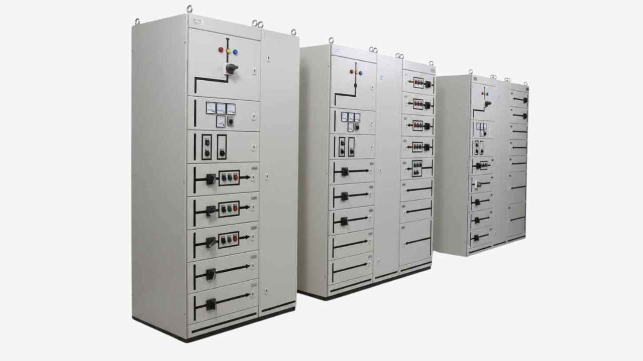
Соединитель для автобусных шпал
Соединительный узел для шин соединяет две шины, питаемые от разных источников питания. Такая конфигурация обычно используется в ситуациях, когда два разных фидера или трансформатора питают отдельные шины.
Такая конфигурация позволяет обеспечить резервное электропитание в случае отказа одного из источников, поддерживает перераспределение нагрузки между источниками питания и повышает общую надежность системы.
Конфигурация "главный-шпал-главный"
Конфигурация Main-Tie-Main (MTM) включает в себя два главных входящих выключателя и один шинный соединительный выключатель, который соединяет шины. Она обладает высокой степенью резервирования, что позволяет гибко переключать нагрузку между источниками питания.
Двойная шина с шинным сцепным устройством
Двойной шинная система Используется две полноценные шины, работающие параллельно. Выключатель-разъединитель шин соединяет две шины и позволяет переключать цепи между ними. Такая конфигурация обеспечивает чрезвычайно высокую надежность и способствует гибкой работе системы.
Как работает шинопровод?
Шинопровод работает путем электрического соединения или изоляции двух секций шины в цепи. распределительное устройство или распределительный щит. В нем используются автоматические выключатели или переключатели для управления потоком электроэнергии между шинами.
Нормальные условия эксплуатации
В большинстве систем распределения электроэнергии шинный соединитель обычно разомкнут (НО). В этом случае трансформаторы или генераторы подают электроэнергию независимо друг от друга на соответствующие участки шин. Соединители здесь выполняют функцию изоляции, предотвращая влияние колебаний нагрузки или неисправностей на одной стороне на другую.
Приблизьте сцепное устройство автобуса
Когда один участок шины необходимо отключить из-за технического обслуживания или неисправности, необходимо замкнуть шинный соединитель. В этот момент автоматический выключатель соединителя физически соединяет две шины вместе, позволяя энергии перетекать от одной шины к другой. Это обеспечивает непрерывное электроснабжение важных нагрузок.
Передача энергии и распределение нагрузки
Когда шинный соединитель замкнут, система обеспечивает распределение мощности между двумя источниками питания или участками шины. Это позволяет осуществлять перераспределение нагрузки или временную балансировку нагрузки. После завершения технического обслуживания или перераспределения нагрузки автоматический выключатель шинного соединителя снова разомкнется, чтобы разъединить шины. Размыкание шинного соединителя также гарантирует, что короткое замыкание или неисправность в одном участке не распространится на другой участок.
Зачем в электрических щитах используются шинные соединители?
Шинопровод позволяет соединять или разъединять два участка шины по мере необходимости, что помогает лучше контролировать поток электроэнергии и работу системы. Преимущества использования шинопровода заключаются в следующем:
Резервирование источника питания
Многие важные объекты используют резервные системы электропитания с несколькими источниками питания, например, с двумя трансформаторами, несколькими генераторами и т. д. Шинопровод может соединять системы при необходимости, гарантируя непрерывное электроснабжение. Если для вашей работы требуется высокая надежность электроснабжения и бесперебойная работа, такая резервная система крайне важна.
Повышенная надежность
Во многих конфигурациях две секции шин питаются от разных трансформаторов или фидерных линий. Если один из источников питания выходит из строя, шинный соединитель отключается и подает питание на обе секции через исправную шину. Это гарантирует, что основные нагрузки продолжают получать питание. Это особенно важно в центрах обработки данных, больницах и производственных предприятиях.
Гибкое управление нагрузкой
В крупных электрических системах ваши потребности в электроэнергии могут меняться со временем. Шинопровод обеспечивает высокую гибкость в управлении электрическими нагрузками. Вы можете передавать нагрузку между трансформаторами через шинопровод, балансировать нагрузку между секциями шин и предотвращать перегрузку одного источника питания. Это существенно повышает эффективность и стабильность системы распределения электроэнергии.
Техническое обслуживание без полного отключения
Шинопроводы позволяют питать часть электросистемы, обеспечивая при этом бесперебойное питание остальной её части. Трансформатор можно отключить для проведения технического обслуживания. Шинопровод можно замкнуть, чтобы подавать питание на нагрузку из другого источника.
Применение шинопроводов в электрических щитах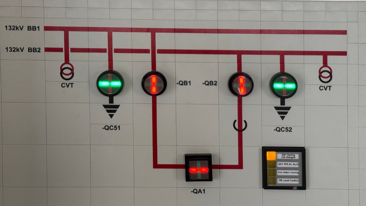
Промышленные производственные предприятия
На промышленных предприятиях обычно используются крупные и сложные системы распределения электроэнергии для питания такого оборудования, как электродвигатели, конвейеры, насосы и производственные линии. Для соединения различных участков шин в главном распределительном щите или центре управления двигателями можно использовать шинные соединители.
Шинопровод позволяет соединять несколько шин на предприятии, перераспределять нагрузки между источниками питания, обеспечивать электропитание во время технического обслуживания оборудования и т.д. Это помогает предотвратить экономические потери, вызванные простоями производства.
Центры обработки данных
Для обеспечения работы серверов, систем хранения данных и сетевой инфраструктуры вашему центру обработки данных необходимо использовать чрезвычайно надежное бесперебойное электропитание. Шинные соединители обычно используются в рамках архитектуры резервированного распределения электроэнергии. Использование шинных соединителей позволяет центру обработки данных обеспечить высокую доступность и отказоустойчивость.
Подстанции и электростанции коммунального хозяйства
Шинопровод можно использовать на подстанциях среднего и высокого напряжения для соединения различных шинных систем и управления потоком электроэнергии между ними. Эти системы могут повысить надежность и эксплуатационную гибкость энергосистемы и имеют жизненно важное значение для сетей генерации, передачи и распределения электроэнергии.
Коммерческие здания и крупные сооружения
Шинные соединители также можно использовать на главных электрических щитах крупных коммерческих зданий, таких как офисные здания, торговые центры и аэропорты. Они позволяют управлять распределением электроэнергии внутри здания, обеспечивая проведение технического обслуживания без прерывания работы. Это полезно для обеспечения надежного электропитания освещения, систем отопления, вентиляции и кондиционирования воздуха, а также других инженерных систем здания.
Часто задаваемые вопросы
В чём разница между сцепным устройством для шин и устройством для разрыва шинных связей?
Шинопроводный соединитель — это автоматический выключатель или коммутационное устройство, используемое для соединения двух секций шин в распределительном устройстве. электрическая панель. Это может облегчить передачу электроэнергии между секциями шин.
Разъединитель шин используется для соединения двух отдельных шин, питаемых от разных источников питания. Обычно он используется для обеспечения резервного питания или для перераспределения нагрузки между независимыми электрическими системами.
Какие типы автоматических выключателей используются в качестве шинных соединителей?
Выбор автоматического выключателя для шинопровода в основном зависит от уровня напряжения и требований системы. К распространенным типам автоматических выключателей относятся воздушные, вакуумные и выключатели на основе гексафторида серы. Для обеспечения безопасности эксплуатации эти автоматические выключатели должны соответствовать номинальному току и допустимой нагрузке короткого замыкания вашей шинопроводной системы.
Требуется ли шинопровод в каждом электрощитке?
Нет. Шинопроводы обычно используются в крупных системах распределения электроэнергии с несколькими шинами или источниками питания. Если у вас небольшой электрический щит с одной шиной и одним источником питания, шинопровод вам не нужен. Если вам требуется резервирование, перераспределение нагрузки или повышение надежности системы, вы можете установить шинопроводы в крупных системах распределения электроэнергии.
Какие факторы следует учитывать при проектировании системы шинных соединителей?
При проектировании системы шинопроводов необходимо учитывать такие технические факторы, как номинальный ток, предельная мощность при коротком замыкании и уровень напряжения. Кроме того, необходимо убедиться, что защитные реле согласованы с другими автоматическими выключателями.
Логика блокировки и управления имеет одинаково важное значение. Это позволяет предотвратить небезопасные переключения между источниками питания. Наконец, необходимо также обеспечить соответствие требованиям к резервированию системы.
Заключительная мысль
Компания KDM, являясь профессиональным производителем электротехнических корпусов на заказ, может предложить вам высококачественные электрические панели. Наши электротехнические корпуса изготавливаются с использованием передовых технологий и высококачественных материалов, что гарантирует вам высокое качество продукции. Если у вас есть особые требования, пожалуйста, свяжитесь с нами. связаться с нами.